
Environmental Corrosion
Soil chemistry, moisture, and galvanic reactions corrode buried copper/GI conductors and electrode rods, increasing resistance and breaking continuity — often without any visible signs above ground.

Thermal & Electrical Stress
Repeated fault currents and overload cycles apply thermal stress on conductor joints and terminations, loosening them over time and introducing dangerous resistance in the earth loop path.

Poor Workmanship & Ageing
Improper crimp joints, unsupported conductor bends, or shallow electrode installations degrade far faster than correctly installed systems — and may never have met design intent from day one.

System Modifications
Plant expansions, equipment upgrades, or load increases can invalidate the original earthing design. Breaker protection settings calculated for the original fault current path become unsafe after modifications.

Grid Islanding
In large substation earth grids, individual grid sections can become electrically isolated (islanded) due to open conductors — leaving equipment in that zone with no fault current return path at all.

Regulatory Compliance
CEA Regulations, IS 3043:2018, and factory/insurance inspectorate requirements mandate periodic verification of earthing system adequacy. Non-compliance carries legal liability and insurance invalidation risk.

Pre-Audit Review
Collection and review of SLDs, earthing drawings, test history, CEA/protection relay records, and previous audit reports.

Site Survey & Inspection
Physical walkdown of all earthing electrodes, conductor strips, risers, joints, earth bars, and bonding connections across the facility.

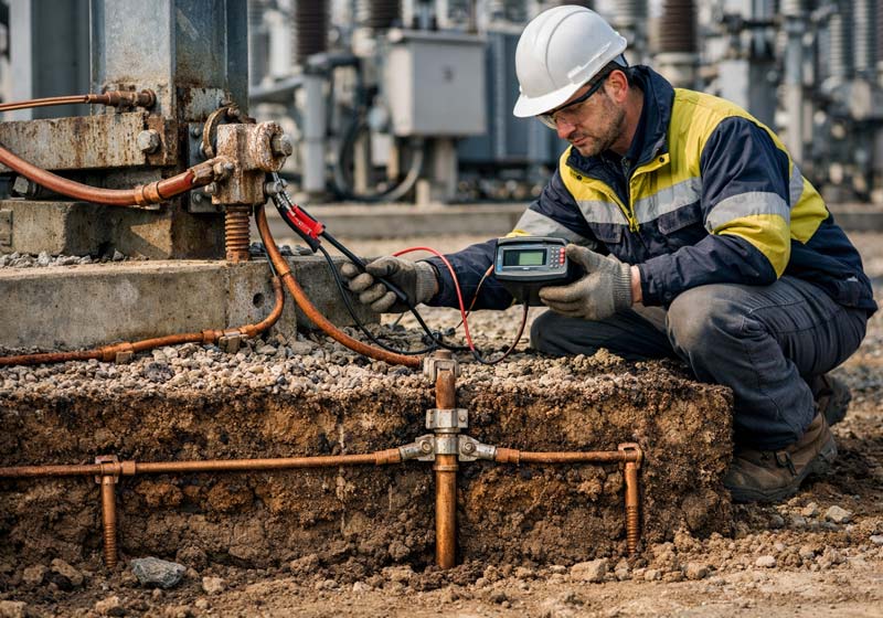
Field Testing
Systematic execution of all applicable tests (soil resistivity, electrode resistance, riser/grid integrity, loop impedance, touch/step potentials) using calibrated instruments on live systems.

Analysis & Modelling
Data analysis against IS/IEEE thresholds, earth grid simulation for EHV systems, and identification of non-compliances and risk-ranked deficiencies.

Report & Recommendations
Comprehensive audit report with photographic evidence, test data, deficiency findings, and prioritised remedial recommendations with compliance roadmap.
Comprehensive Audit Report

Defect Location Map

Touch & Step Potential Report

Prioritised Recommendations
Comprehensive Audit Report

What Our Audit Identifies & Resolves

Power Substations
EHV/HV/MV AIS & GIS substations — transmission, distribution, and pooling stations.

Power Generation Plants
Thermal, hydro, and gas-based power stations where reliable earth grid integrity is safety-critical.

Solar & Wind Farms
Utility-scale renewable plants with extensive DC array earthing, inverter earthing, and grid connection substations.

Oil, Gas & Petrochemical
Hazardous area facilities requiring flawless earthing and bonding for static charge and explosion prevention.

Manufacturing & Process Plants
Continuous process industries where nuisance tripping from earthing failures causes costly production disruptions.

Data Centres
Mission-critical facilities where ground reference quality directly affects sensitive IT equipment reliability.

Metro Rail & Transport
Traction power systems with stray DC current risks requiring comprehensive earthing and bonding assessment.

Commercial & Institutional
Hospitals, IT parks, airports, and large commercial complexes requiring statutory electrical safety compliance.

Enhanced Personnel Safety
Eliminates unsafe touch and step potentials that can cause fatal shock — particularly during earth fault conditions in substations and switchyards.

Reliable Protection System Operation
Ensures breakers trip within safe times during faults, preventing fire, short-circuit escalation, and equipment damage across the electrical system.

Reduction in Equipment Failures
Studies indicate a 38–40% reduction in electronic equipment and relay failures after grounding system deficiencies are corrected.

Regulatory & Insurance Compliance
Demonstrates due diligence under CEA Regulations, IS 3043, and factory/inspectorate requirements — essential for licence renewals and insurance validity.
Cost-Effective, Targeted Remediation
Pinpoint defect location maps allow precise excavation and repair at specific points — eliminating the need for expensive blanket re-earthing of entire grid sections.

Qualified Expert Team
Chartered Engineers (IEI), NEBOSH-certified professionals, Class A Licensed Electrical Supervisors — with experience on India's largest substations and power plants.
Live System Testing — No Shutdown
Specialised non-intrusive instrumentation enables complete earthing audits on energised systems, eliminating production disruption and shutdown costs.

National & International Standards
All recommendations reference IS 3043, IEEE 80, BS 7430, CEA Regulations, and CBIP Manual 339 — ensuring both domestic compliance and international best practice.

Pinpoint Defect Location
We don't just tell you something is wrong — we tell you exactly where. Precise GPS/plan-referenced defect marking minimises the cost of remediation.

Head Office
India (New Delhi) · UAE (Dubai) · USA

Phone
+91-9810827158 / +91-9818257504

info@wireconsultants.com