Professional Protection Coordination Study: Ensuring System Selectivity and Reliability
In modern power distribution systems, electrical faults are an inherent risk. The technical integrity of a facility depends on the Protection Coordination Study (Relay Coordination), which ensures that protective devices respond with surgical precision to isolate disturbances.
Across the Indian electrical landscape, the integration of distributed energy resources (DERs), complex backup topologies, and non-linear loads has increased the necessity for rigorous technical analysis to prevent cascading failures and mal-operation.
What is a Protection Coordination Study?
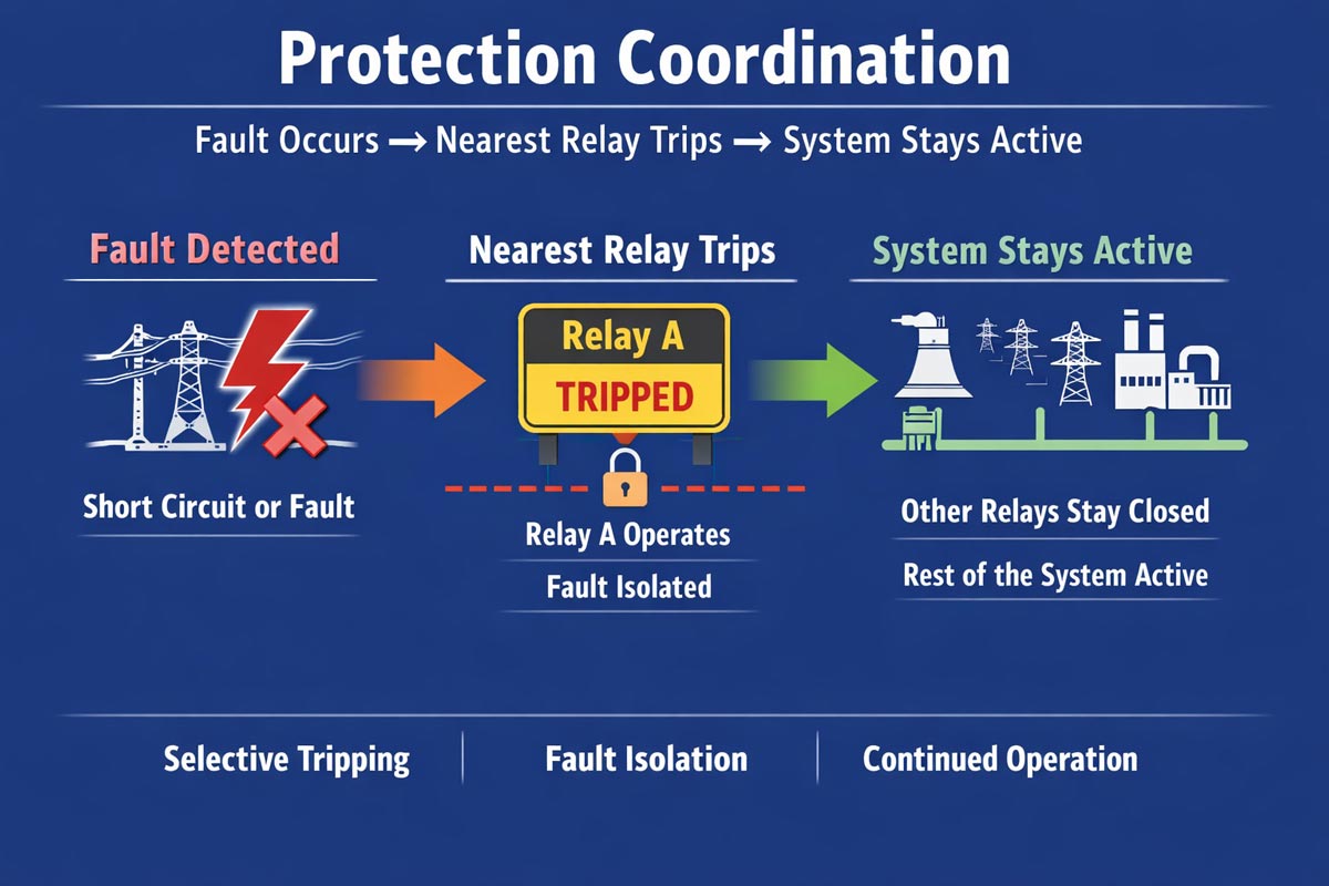
A protection coordination study is a formal engineering analysis utilizing Time-Current Characteristic (TCC) curves to determine the optimal settings for protective devices. The primary goal is Selectivity: ensuring the device closest to the fault operates first, thereby minimizing the “dark zone” and maintaining power to healthy sections.
In a technically sound system, the hierarchy follows:
- Primary Protection: The localized device (e.g., downstream ACB/MCCB or Relay) clears the fault within predetermined cycles.
- Backup Protection: Upstream devices (e.g., VCBs) operate only after a specific Coordination Time Interval (CTI) if the primary device fails.
- Sensitivity: Relays must be set high enough to allow for inrush currents (transformer magnetization/motor starting) but low enough to detect minimum fault levels.
The Critical Role of Coordination
1. Optimization of System Selectivity
Without coordination, a minor fault at a motor feeder can trigger the main incoming breaker. A study ensures that the discrimination between devices prevents unnecessary upstream tripping, protecting production continuity.
2. Mitigation of Incident Energy and Arc Flash
Prolonged fault clearing times increase the Arc Flash Incident Energymeasured in cal/cm2. Proper settings, aligned with IEEE 1584 and NFPA 70E, reduce the duration of the fault, thereby lowering the risk to personnel and equipment.
3. Thermal and Mechanical Asset Protection
Excessive fault duration subjects’ transformers and cables to thermal stress and mechanical forces. Coordination ensures faults are cleared before reaching the damage curves of expensive assets.
4. Regulatory and Standard Compliance
In India, system design must adhere to stringent domestic and international frameworks:
- CEA (Measures relating to Safety and Electric Supply) Regulations: Mandatory guidelines for the operation and maintenance of electrical systems.
- IS/IEC 60255: Standards for electrical relays.
- IEEE 242 (Buff Book): Recommended practice for protection and coordination of industrial and commercial power systems.
- IEEE 399 (Brown Book): Standard for power system analysis.
Technical Scope of the Study
A comprehensive study involves high-fidelity modelling and simulation:
| Phase | Description |
| Data Acquisition | Collection of transformer impedance (Z%), cable lengths/X-R ratios, and manufacturer-specific relay/breaker curves. |
| Short Circuit Analysis | Calculation of Isc (Symmetrical and Asymmetrical) as per IEC 60909 to determine interrupting ratings. |
| TCC Plotting | Graphing of Time vs. Current on a log-log scale to visualize the “protection envelope” and identify overlaps. |
| Setting Implementation | Calculation of Pick-up current, Time Dial Settings (TDS), and Instantaneous (High-set) values. |
Common Protection Gaps in Indian Infrastructure
Many facilities suffer from “nuisance tripping” or “blind spots” due to:
- Curve Overlap: No margin between downstream fuse and upstream relay curves.
- Incorrect CT Ratios: Leading to saturation during high-magnitude faults.
- Legacy Modifications: Adding new loads without re-calculating the Total Clearing Time.
- Utility Miscoordination: Failure to coordinate the internal main breaker with the Utility (State DISCOM) protection settings.
Engineering Support by Wire Consultancy
Wire Consultancy provides expert-led protection studies tailored to the specific constraints of the Indian grid and industrial environments. We utilize industry-standard software (such as ETAP or SKM) to deliver:
- Verified Protection Settings: Precise values for Overcurrent (50/51) and Earth Fault (50N/51N) elements.
- CT Adequacy Checks: Ensuring current transformers do not saturate under maximum fault conditions.
- Implementation Roadmap: Clear, actionable settings for site engineers to program into Numerical Relays.